Seth's House
DIY 12 Volt PID Smoker Controller
While my last PID controller build is extremely versatile and a multi-tasker, the only drawback is that it requires AC power to operate. I recently put together an Ugly Drum Smoker, which unlike my CharGriller, is (somewhat) portable. The need came up for me to build a PID + blower fan rig that could be powered from AC, but also portable power if necessary. Luckily for me, the JLD612 comes in a 12 volt model, and with a background in car electronics, this 12-volt setup was a cake walk. This particular build is not a multi-tasker, just a straight up smoker controller.
While at home, I can power it with a standard 12 volt wall wart power supply, and when on the go, I can use a jump pack, or even a car battery and some alligator clips.
Just like anything I post, this is the way *I* built this unit. Is it the only way to do it? Nope. Is it the absolute best? Probably not. But it works for me, and should give you, the reader, enough information to help you figure out something on your own.

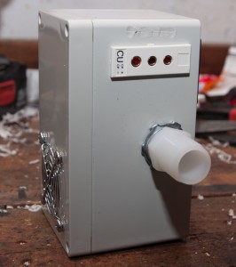
Completed unit
Parts List
Here are the parts I used for my build – many have “See Power Input Notes below” because you can pick and choose whatever type of physical input power connector you wish.. this is just what I ended up with myself. There are infinite choices, many better ones than I have used, you’re free to do what you wish.
- 1x JLD-612 (12 Volt Model) PID Temperature Controller – $36.50 US
- 1x Digikey P/N 603-1177-ND 15.3CFM 12V Blower Fan – $15.53 US
- 1x Digikey P/N HM923-ND Project Box – $15.13 US
- (See Power Input Notes below) 1x Digikey P/N T1061-P5P-ND 12volt Power Supply – Size M Connector- $14.70 US
- 1x PT100 Sensor Probe – $15.50 US
- 1x TPJ-U-F thermocouple panel jack – $4.70 US
- 1x OTP-U-M thermocouple male plug – $3.90 US
- (See Power Input Notes below) 1x Digikey P/N SC-1047-ND *OR* Radio Shack 274-1563 Size ‘M’ Panel Connector ~$4 US
- (See Power Input Notes Below) 1x DigiKey P/N 763KSW-ND *OR* Radio Shack 274-1569 Size ‘M’ DC Power Plug ~$4 US
- (See Power Input Notes Below) 1x 12 Volt SPST Switch (optional – have a look at Digikey’s catalog or a Radio Shack Example that I used) ~$4 US
- Standard Automotive 12 volt relay (something like this) – ~$5 US at any Auto Parts store, I had some laying around
- (Optional) 2x Barrier strips, at least 3 positions – like these – don’t forget the jumpers
- 1″ ID x 3/4″ MIP Nylon Hose Barb (Home Depot part A-625 in the nylon hose part area)
- Hose to connect to your smoker – I used 1″ ID plastic bilge hose from Home Depot
- (Optional) 1x Warning light, 12volt powered, if you plan on using the built in alarm functions of the JLD612
- 1x Fan guard, salvaged from parts laying around. Digikey’s fan guard section
- 1x Fuse holder Example 1 Example 2 – along with a 1amp 12 volt fuse
- M4 nuts and bolts to mount the fan
- Various quick disconnect crimp connectors. If you have a well stocked electrical connector box for automotive stuff, that will get you through it
- Hot glue gun to mount components like the barrier strips
- Dremel tool / drill, to mount everything in the box
Power Input Notes
I chose to use a wall wart for my 12 volt power source (when AC is available), and also put an on/off switch for the whole unit. You don’t need to use either, but you can if you want. I actually bought the wall wart, but, if you go digging in your junk pile at your residence, you will probably find a 12V power supply that works just fine for you from an old phone or router. You may also decide to use this away from any type of power source ever, and just use a 12 Volt battery or jump starting pack (my whole reason for building a 12 volt PID in the first place) – in that case, pick whatever type of physical power input plug works for you. Digikey and Radio Shack have extensive choices, have fun with their catalogs.
Relay Talk
The JLD612 has two different methods of activating the heating device, in our case, a blower fan. It can use the built-in relay J2, or it can use the built in SSR (solid state relay) control. Since I had relays laying around, my build uses the J2 option. If you want to use an SSR, by all means, go right ahead. Sample units are here and here. The advantage of using an SSR is that you could use the built in alarm functions of the JLD612 to activate warning lights (anything, really) on low or high temperature conditions, while using the SSR output for the PID control. In my setup, J2 is tied up with PID control, so only J1 is available for alarm output.
Fan Output – Rectangle in to a round hole?
When I first envisioned this thing, my only real question without having the parts in my hand was if the rectangular output of the fan would mate up to the circular hose barb – more importantly, if I would have to block off the air from the fan exit so that it would only blow out of the hose barb, and not just blow inside the project box. The answer is, no, I did not have to block off any of the fan exit. When I mounted everything, I lined it up as best I could, and plenty of air comes out of the barb without any sort of special ductwork. I am actually impressed at the amount of air that this fan moves.
Component Mounting
I mounted the JLD612 and thermocouple jack first. Make templates with cardboard for the JLD612 and thermocouple panel jack. Transfer these templates to the plastic project box and start cutting. My JLD612 is mounted high on the box as far as I can go, while still being able to attach the wire terminals for pins 6-10 on the JLD612, and leaves enough space for the fan to fit in the box.
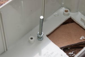
Closeup of fan mounting post
Once the JLD612 is in place, I worked on mounting the hose barb, which is the fan output. I first placed the fan in the box and mounted it as high as I could without interfering with the JLD612, but also clearing the plastic ridge inside the box. I then marked its two mounting holes and drilled holes in the plastic box. Using a 2″ M4 machine screw, I secured the screw through the box, with a nut on the inside. I then added 1 nut to each screw, so the fan stood off of the box by about a 1/4″ (eyeballed). Once the fan was mounted, I marked the center location of the fan output, and drilled the hole for the hose barb. Mount the hose barb with the conduit nuts, then adjust the location of the fan so that it is centered in the host barb opening. Once it’s centered, add another nut to each screw to hold the fan securely.
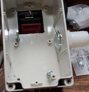
Mounting hole for JLD612. Posts for the fan, and barb mounted.
The switch, warning light, and power input jack all mount through drilled holes. The relay inside mounts on one of the fan screw posts with a nut, just so it’s not bouncing around.
Wiring
- Input voltage comes in through the M connector. Negative (aka ground in the 12V world) goes straight to the Negative Barrier Strip. +12v goes through the switch, to the fuse holder, then to the +12V Barrier Strip.
- Supply +12V from barrier strip to the JLD612 on pins 1, 4*, 13, and the relay pin 30
- Supply -12V from barrier strip to the JLD612 pin 2, Relay pin 85, fan negative, warning light negative*, and your switch if you chose a lighted one
- Connect the red pin of your thermocouple to pin 8 of the JLD612 (through panel jack)
- Connect each blue pin of your thermocouple to pin 9 and 10 of the JLD612 (through panel jack)
- Connect pin 14 of the JLD612 to pin 86 of the relay
- Connect pin 87 of the relay to the fan positive input
- Connect pin 5 of the JLD612 to your warning light +12v*
*Warning light not pictured at the time of writing this
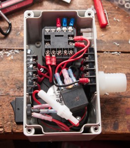
Everything mounted and wired
That’s about it as far as construction goes! You will want to familiarize yourself with the PID controller manual and set all of the configuration parameters properly on the first use. My settings are as follows on the ‘0089’ set menu:
- IntY = PT 10 0 (Pt100 thermocouple, this setting will show temp in .1 increments)
- OutY = 1 (PID controls J2 )
- rd = 0 (heating control)
- CorF = 1 (Fahrenheit)
On the ‘0001’ set menu, I have the following settings, for the high temperature warning light to come on at 230F and go out at 228F:
- AH1 = 230
- AL1 = 228
On the ‘0036’ set menu, I have the following setting due to me using a mechanical relay. For an SSR, leave this alone:
- ot = 5 (Recommended to use 5-15, TBD what setting I end up with. This keeps the relay from cycling so much and wearing out)

Maiden voyage, on the UDS
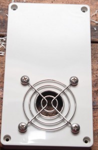
Fan finger screen
Side view, thermocouple plug and hose barb. Don’t mind my dremel oops.
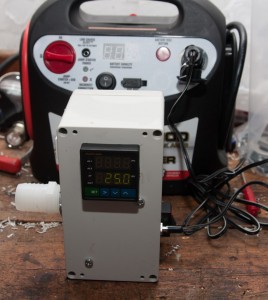
Tested the controller out with a cigarette lighter plug.. works great off a jump pack

February 18th, 2013 at 9:44 pm
Looks great. Do you happen to have a wiring diagram?
Thanks
February 18th, 2013 at 9:53 pm
Nope, but the wiring connections are simple and described above.. if you need help, let me know
March 12th, 2013 at 12:17 pm
Hey Iceman,
I am going to build one of these for my kamado cooker. The parts are on order. Thanks for the description and pictures. One of the things that has always been unclear when I was investigating the PIDs is that they do not actually run the fan; they must be connected to some type of relay; either a relay or a solid state relay. A person can buy a PID that has connections for a relay, a solid state relay or both types. The descriptions of PID make this very confusing. I was never sure if the relay or SSR was incorporated into the PID. The description of the PID states the type of relay that can be used with the PID. You write up help me understand that.
Now for a question. With the fan off, is there still enough air flowing through the box and tube to the smoker to increase the temperature? Do you need a little flapper to stop the air flow that might occur when the fan is off?
With my cooker, I keep my lower intake vent shut or just slightly cracked to maintain a 225 degree temperature. I am concerned about air flow with the fan off.
Nice job on the write up!
March 12th, 2013 at 5:26 pm
Hi Tom,
Thanks for stopping by. I have only used this PID+Fan on my Ugly Drum Smoker so far, which is very well sealed. I don’t have anything to stop airflow, and temperature control is no issue — if too much air was getting by, I’d have a constant problem with high temperatures (air = more fire = more heat). So, I think it would be safe to say, you don’t need anything to stop airflow, but, every smoker is different.
On my CharGriller, I have the same PID but slightly different setup, see my other PID build for details. I don’t have anything to stop airflow on that, and same thing – no problem. That thing is not sealed well whatsoever, so, plenty of air leaking in, but I still have precise temp control.
I’ve read about guys on the BBQ Bretheren using wood stove gaskets to help seal up cracks, to insure that your fan inlet is the only possible place that air can get in. The better your vessel is sealed, the more precise temperature control you will experience.
April 8th, 2013 at 10:40 pm
I had a question. I have built something almost identical to what you have built here. I am having issues with getting it wired properly. I have not used a barrier strip or any kind of relay. Bear with me because I am very much a newbie. When I power on the PID an set the parameters the JLD612 just constantly cycles the fan on and off for a few seconds regardless of the temp readings or setting. I am stumped because looking at yours and looking at mine there are not any glaring differences on how we have them hooked up. Please if you wouldn’t mind give me some insight. Is the relay required? or the barrier strips? Any input would be greatly appreciated! Thanks!!
April 10th, 2013 at 12:09 pm
Hi Luke,
Not sure what the current draw is on your fan, but I would use a relay if I were you – the PID output is not meant to directly power a fan, from what I gather.
April 10th, 2013 at 11:05 am
Love the design, I plan on building one for my drum smoker this summer. It might be overkill but there is one feature that I am trying to add: integrated data logging. As a basic concept, I’d like to convert thermocouple voltages to digital values and save to an ascii file every 30 seconds or so. No good idea yet of how to get the data out after (homebrew USB port? Is that even possible?) It gets messy from there: another circuit board with a peripheral interface controller (PIC), analog-to-digital converter, memory module, etc. Unless there is some way to leverage the PID that is already in the build… but I dont’t see a way. I’m rusty on these topics. Any thoughts?
April 10th, 2013 at 12:08 pm
Hi Shane,
If I were you, I’d look into something called a HeaterMeter on tvwbb.com – you may find that more useful 🙂 I have the parts for one, have not begun assembly yet. This controller is just a standalone, ‘dumb’ unit, without the bells and whistles, but works great!
April 10th, 2013 at 1:12 pm
Iceman,
HeatMeter looks amazing! I was thinking WAY too small. Thanks so much for the info… even though you probably just cost me many, many nights & weekends. 🙂
April 10th, 2013 at 1:13 pm
(Insert joke about “You can be my wingman any time.”)
April 10th, 2013 at 2:05 pm
The fan I have is rated at .53 amps. And after some reading I believe you are right about the controller not being able to carry the load continuously. Which even to my newbie ears seems to explain my problem. Seeing as I can pick one up fairly cheaply I will be hooking my PID the same way you have explained here. I have mine set up with a 12V battery pack that I got off the good ole eBay that allows for total portability while still allowing me to hook it up to constant power from the wall wart when available. Just wanted to say thanks! Your build has been a huge help!
April 10th, 2013 at 2:10 pm
Cool man, let me know how you make out.
How did you come across this by chance? Just wondering.
-Seth
April 10th, 2013 at 5:58 pm
Just typed “DIY 12v PID” into google and your site was on the first page while I was researching for my build. Your build was the only one almost identical to what I had in my mind to build. Thanks again!
April 10th, 2013 at 10:42 pm
good stuff. Enjoy!
May 22nd, 2014 at 7:51 pm
hey bud have any of these ever been used on a reverse flow smoker 250 gallon tank
March 3rd, 2015 at 10:37 am
@Luke, I currently have the same issue you described. Did using a SSR fix your issue of the fan turning on and off constantly?